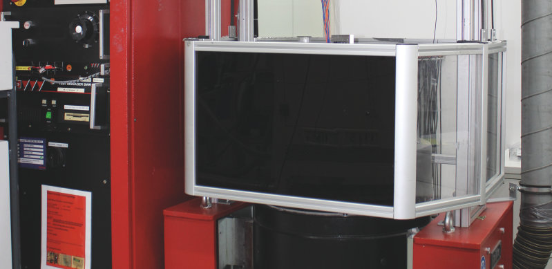
Vibration Analysis
A product is exposed to various mechanical loads during its product life cycle. This may concern both transport and normal operation. To ensure that the product is able to withstand such loads, they are simulated in the test laboratory with vibration tests. Electro-dynamic shakers are implemented to excite vibrations in the component for vibration analysis and modal analysis. These shakers are also used for service life tests, where high frequencies must be applied.
We offer the following specific test procedures:
- Vibration test (sinusoidal, noise)
- Vibration test with temperature application (Shake&Bake)
- Resonance analysis
Test modes:
Test modes are subdivided into:
- Sinusoidal vibration = deterministic algorithmic vibrations
- Random or noise excitation = stochastic vibrations
- Shock excitation = single knocks or hits
The differences:
With sinusoidal signals, the energy for each frequency is generated individually and is then temporally and sequentially applied over a frequency band. With noise signals, energy is generated for all frequencies simultaneously and transmitted.
This means that with sinusoidal signals, the resonances of a structure are excited only once, whereas with noise all resonances are continuously excited. Therefore with sinusoidal excitation the resonators (mass spring system) for a test object are also loaded to a greater degree with identical energy content (unnaturally).
Shock excitement refers to the excitation of a test object with knocks or hits. With this process, many frequencies are excited simultaneously with a single hit.
RMS SWR 3710 | ||
|---|---|---|
| Max. force | ||
| Shock | 15 KN | as=1660m/s2 |
| Sinus | 7,5 KN | as=833m/s2 |
| Noise | 3,5 KN | as=173m/s2 |
| Max. mass | 250 kg | |
| Max. peak path | 18 mm | |
| Unloaded weight | 10 kg | |
RMS SWR 6005 | ||
|---|---|---|
| Max. force | ||
| Shock | 10 KN | as=1000m/s2 |
| Sinus | 11,7 KN | as=1170m/s2 |
| Noise | 8,10 KN | as=1170m/s2 |
| Max. mass | 250 kg | |
| Max. peak path | 18 mm | |
| Unloaded weight | 9 kg | |
S 50501 | ||
|---|---|---|
| Max. force | ||
| Shock | 10 KN | as=65 m/s2 |
| Sinus | 11,7 KN | as=513 m/s2 |
| Noise | 8,10 KN | as=33 m/s2 |
| Max. mass | 25 kg | |
| Max. peak path | 25,4 mm | |
| Unloaded weight | 1,6 kg | |
Resonance measurement station | ||
|---|---|---|
| Frequency range | 25 kHz | |
| Measurement precision | +/- 10 Hz | |
